


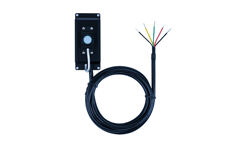
Real-time acquisition and monitoring of UV power and energy Standard RS485 communication interface/ MODBUS communication protocol Directly communicate with PLC, HMI, computer and other devices
The LS129 intelligent communication UV digital probe features a standard RS485 communication interface and MODBUS communication protocol, enabling direct communication with PLCs, HMIs, and computers. The detector and controller adopt a split design, making it convenient for real-time acquisition and monitoring of UV power and energy. Currently, 7 types of UV digital probes are available, which can be selected according to the UV spectral range and application industry.
UV Digital Probe Selection
| Probe Model | Spectral Response | Application |
|---|---|---|
| UVALED | 340nm-420nm | UV curing, UV LED surface light source intensity and energy measurement |
| UVA | 315nm-400nm | UV curing, high-pressure mercury lamp intensity and energy measurement |
| UVC | 230nm-280nm | 254nm UV germicidal mercury lamp intensity and energy measurement |
| UVALED-X1 | 340nm-420nm | Fiber optic straight probe, high-temperature UV LED surface light source |
| UVA-X1 | 315nm-400nm | Fiber optic straight probe, high-temperature mercury lamp |
| UVALED-X2 | 340nm-420nm | Fiber optic right-angle probe, high-temperature UV LED surface light source |
| UVA-X2 | 315nm-400nm | Fiber optic right-angle probe, high-temperature mercury lamp |
Probe Parameters
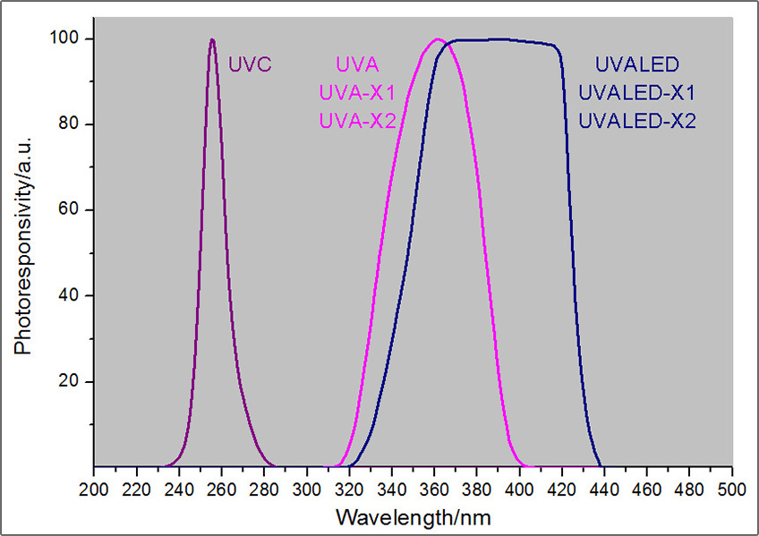
Spectral Response Curve
1.Station No
The UV digital probe supports the standard MODBUS protocol, with a default communication address of “1”. The address can be modified via the HMI debugging tool or communication protocol. Address range: 1-247.
2.Baud Rate
The default baud rate is 9600 bps. It can be modified via the HMI debugging tool or communication protocol. Available options: 4800, 9600, 19200, 38400.
3.Communication Protocol
Supports the standard MODBUS protocol. Measurement data can be read and communication parameters (address and baud rate) can be set via the protocol. For detailed commands, refer to the "LS129 Digital Probe Communication Protocol".
4.Probe Wiring
Feature
Ultra-Compact Detector Design
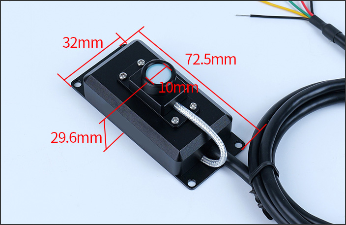
The detector is extremely compact and can be installed separately or integrated with the controller using screws for combined measurement.

Probe Dimensions
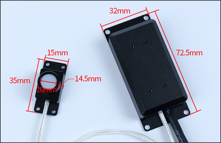
UVA/UVALED probe dimensions
UVC probe dimensions
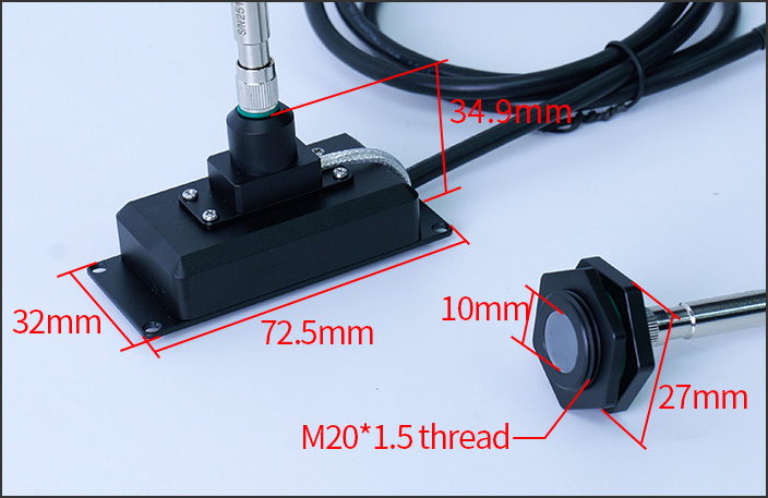
UVA-X1/UVALED-X1 probe dimensions
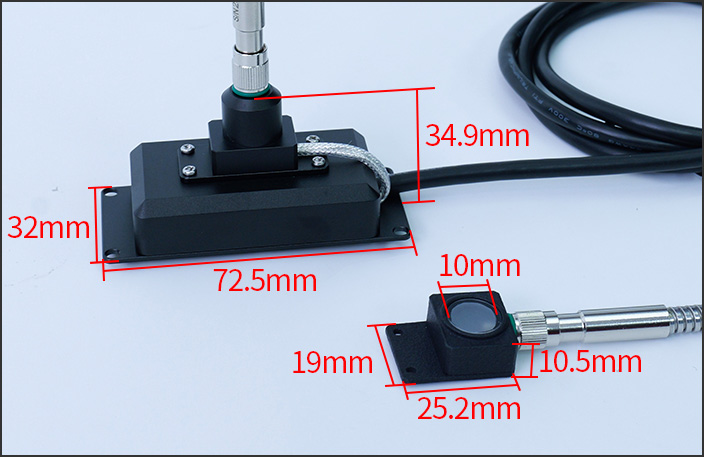
UVA-X2/UVALED-X2 probe dimensions
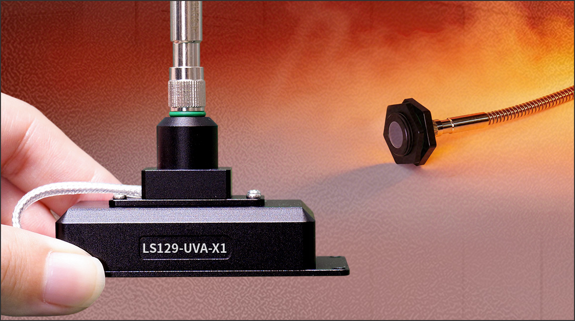
Fiber Optic Probes for High-Temperature Curing Detection
Fiber optic probes are available in straight and right-angle versions, designed for high-temperature environments such as UV LED sources and high-pressure mercury lamps. They support continuous online monitoring at temperatures up to 300°C.
Supports Multi-Device Networking
Equipped with a standard RS485 communication interface and MODBUS protocol, enabling multiple devices to be networked and directly connected to PLCs, HMIs, and computers for online monitoring.

Real-time Online Monitoring of Power and Energy
Simply align the detector with the UV source to measure real-time UV intensity and accumulated energy at the test point.
Wide Power Supply Range
The UV digital probe supports a wide DC power supply range of 5-24V, making it highly convenient for industrial applications.
Debugging tools
Three Optional Debugging Tools
Note: HMI, RS232 converter, and USB converter are not standard accessories and can be purchased separately.
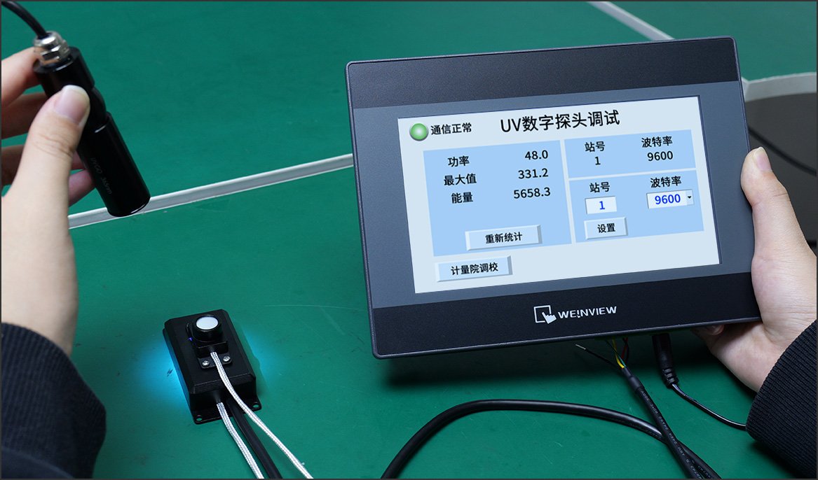
1.HMI for debugging (optional)
Used to view probe data and set address and baud rate during debugging.
2.RS232/RS485 converter (optional)
Used for communication protocol debugging.
3.USB converter (optional)
Used to convert RS485 to USB for connecting to a computer and reading data.
Certifications and Standards
JJG 879-2015 Verification Regulation of Ultraviolet Radiometers
WST 367-2012 Regulation of disinfection technique in healthcare settings
QB/T 2826-2017 Ultraviolet curing offset ink

LS129 Calibration Certificate